วันพฤหัสบดีที่ 7 กุมภาพันธ์ พ.ศ. 2562

โครงงานที่ 19


void alarm(void);
main()
{
TRISB = 0xF0;
while(1)
{
  PORTB.F2=0;
  PORTB.F3=0;
   while(PORTB.F4==0)
   {
    while(PORTB.F6==1)
    {
     PORTB.F2=1;
     alarm();
     }
     }
     while(PORTB.F5==0)
     {
      while(PORTB.F6==1)
      {
       PORTB.F3=1;
       alarm();
         }
        }
       }
      }

void alarm(void)
{
  int i ;
  PORTB.F1 = 1;
  for(i=0;i<500;i++)
   {
   PORTB.F0=1;
   Delay_us(500);
   PORTB.F0=0;
   Delay_us(500);
   }
 PORTB.F1=0;
 for(i=0;i<150;i++)
 {
   PORTB.F0=0;
   Delay_us(1000);
    }
  }


โครงงานที่ 10


void alarm(void);
main()
{
TRISB = 0xF0;
while(1)
{
  PORTB.F2=0;
  PORTB.F3=0;
   while(PORTB.F4==0)
   {
    while(PORTB.F6==1)
    {
     PORTB.F2=1;
     alarm();
     }
     }
     while(PORTB.F5==0)
     {
      while(PORTB.F6==1)
      {
       PORTB.F3=1;
       alarm();
         }
        }
       }
      }

void alarm(void)
{
  int i ;
  PORTB.F1 = 1;
  for(i=0;i<500;i++)
   {
   PORTB.F0=1;
   Delay_us(500);
   PORTB.F0=0;
   Delay_us(500);
   }
 PORTB.F1=0;
 for(i=0;i<150;i++)
 {
   PORTB.F0=0;
   Delay_us(1000);
    }
  }


โครงงานที่ 3


void beep(void);
main()
{
 int timel,time2;
 TRISB = 0xF0;

  while(1)
 {
  PORTB.F1=0;
  PORTB.F2=0;
  PORTB.F3=0;
 while (~PORTB.F4&PORTB.F5&PORTB.F6)
  {
   PORTB.F1=1;
   PORTB.F2=0;
   PORTB.F3=0;
   for(timel=0;timel<20000;timel++)
   {
   while(PORTB.F4&~PORTB.F5&PORTB.F6)
   {
    PORTB.F1=1;
    PORTB.F2=1;
    PORTB.F3=0;
    for(time2=0;time2<10000;time2++)
    {
    while(PORTB.F4&PORTB.F5&~PORTB.F6)
        {
         PORTB.F1=1;
         PORTB.F2=1;
         PORTB.F3=1;
         beep();
         Delay_ms(1000);
         }
         }
       }
       }
      }
     }
   }
void beep(void)
{
 int i ;

 for(i=0;i<200;i++)
 {
  PORTB.F0=1;
  Delay_us(200);
  PORTB.F0=0;
  Delay_us(200);
 }

}

งานที่ 20 https://circuitdigest.com/microcontroller-projects/7-segment-display-interfacing-with-8051

7 Segment Display Interfacing with 8051 Microcontroller

EMBEDDED
ByJayant 8
7 Segment Interfacing with 8051 Microcontroller (AT89S52)7 Segment Display Interfacing with 8051 Microcontroller (AT89S52)
Seven segment displays are important display units in Electronics and widely used to display numbers from 0 to 9. It can also display some character alphabets like A,B,C,H,F,E etc. In this tutorial, we are going to learn how to interface a 7 segment display with 8051 microcontroller. We are using AT89S52 microcontroller from 8051 series.

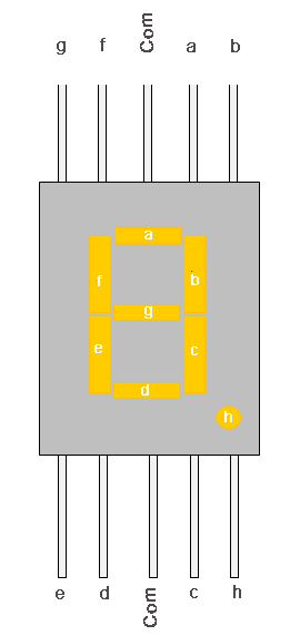
Before interfacing, we should learn about 7 segment display. It’s the simplest unit to display numbers and characters. It just consists 8 LEDs, each LED used to illuminate one segment of unit and the 8th LED used to illuminate DOT in 7 segment display. We can refer each segment as a LINE, as we can see there are 7 lines in the unit, which are used to display a number/character. We can refer each line/segment "a,b,c,d,e,f,g" and for dot character we will use "h". There are 10 pins, in which 8 pins are used to refer a,b,c,d,e,f,g and h/dp, the two middle pins are common anode/cathode of all he LEDs. These common anode/cathode are internally shorted so we need to connect only one COM pin.
7 Segment Display
There are two types of 7 segment displays: Common Anode and Common Cathode:
Common Anode: In this all the Negative terminals (cathode) of all the 8 LEDs are connected together (see diagram below), named as COM. And all the positive terminals are left alone.
Common Cathode: In this all the positive terminals (Anodes) of all the 8 LEDs are connected together, named as COM. And all the negative thermals are left alone.
Types of 7 Segment Displays

Circuit Diagram and Working Expalation

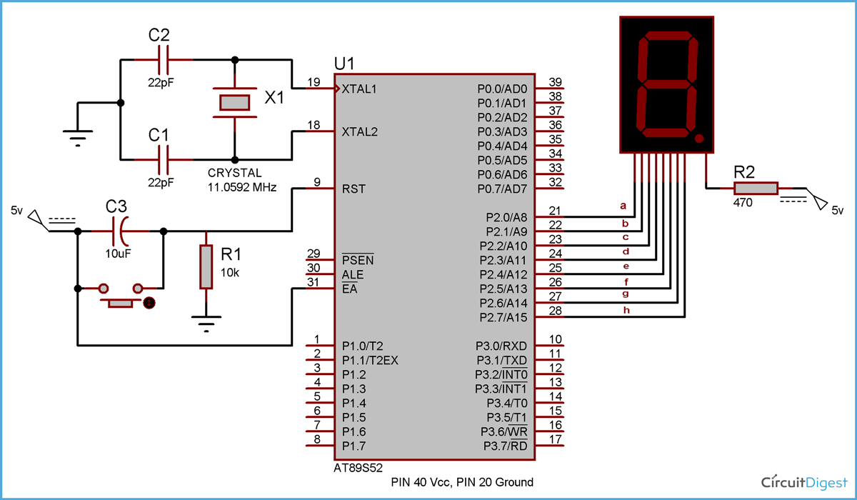
Here we are using common anode type of 7 segment because we need to connect LEDs in reverse. As we know that microcontroller doesn’t provide enough power to glow the LED so we need to connect LED’s cathode to microcontroller pin and LED’s anode to power supply. You can understand this negative logic concept in this article “LED Interfacing with 8051 Microcontroller”. You should also read this article to understand the basic connection of microcontroller like crystal and reset circuitry.
 Circuit Diagram for 7 Segment Interfacing with 8051 Microcontroller
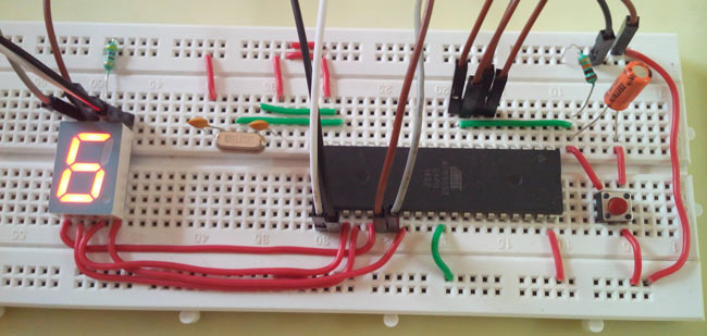
As shown above the circuit diagram for interfacing 7 segment display with 8051 microcontroller, we have connected a,b,c,d,e,f,g,h to pins 2.0 to 2.7 means we are connecting 7 segment to port 2 of microcontroller. Now suppose we want to display 0, then we need to glow all the LEDs except LED which belongs to line “g” (see diagram above), so pins 2.0 to 2.6 should be at 0 (should be 0 to TURN ON the LED as per negative logic) and pin 2.7 and 2.8 should be at 1 (should be 1 to TURN OFF the LED as per negative logic). So the LEDs connected to pins 2.0 to 2.6 (a,b,c,d,e,f) will be ON and LEDs connected to 2.7 and 2.8 (g and h) will be OFF, that will create a “0” in 7 segment. So we need bit pattern 11000000 (Pin 8 is the highest bit so starting from P2.7 to P2.0), and the HEX code for binary 11000000 is “C0”. Similarly we can calculate for all the digits. Here we should note that we are keeping “dot/h” always OFF, so we need to give LOGIC “1” to it every time. A table has been given below for all the numbers while using Common Anode 7 segment.
Digit to Display
h g f e d c b a
Hex code
0
11000000
C0
1
11111001
F9
2
10100100
A4
3
10110000
B0
4
10011001
99
5
10010010
92
6
10000010
82
7
11111000
F8
8
10000000
80
9
10010000
90

Code Explanation

We have created ms_delay function to provide the delay in milliseconds, this delay is usually provided in any microcontroller program so that microcontroller can complete its internal operation.

Then we have created an array of the hex codes for 0 to 9 (see table above), and finally we have sent the hex codes to the port 2, which is connected to common anode 7 segment. So in this way the numbers are shown on the 7 segment display.

Now we have only 4 ports in microcontroller and what if we want to show the data in more than four 7 segments?? To solve this problem, Multiplexing technique comes into picture. We need to multiplex multiple 7 segment units. Also read interfacing 7 segment display with AVR microcontroller.
Code
// Code for 7 Segment Display Interfacing with 8051 Microcontroller (AT89S52)
#include<reg51.h>
void msdelay(unsigned int time)  // Function for creating delay in milliseconds.
{
    unsigned i,j ;
    for(i=0;i<time;i++)    
    for(j=0;j<1275;j++);
}
void main()
{
    unsigned char no_code[]={0xC0,0xF9,0xA4,0xB0,0x99,0x92,0x82,0xF8,0x80,0x90}; //Array for hex values (0-9) for common anode 7 segment
    int k;
    while(1)
    {
        for(k=0;k<10;k++)
        {
         P2=no_code[k]; 
         msdelay(100);
        }
    }
}

งานที่ 19 https://circuitdigest.com/microcontroller-projects/getting-started-with-8051

Getting Started with 8051 Microcontroller

EMBEDDED
ByJayant 10
Getting Started with 8051 MicrocontrollerGetting Started with 8051 Microcontroller
If you are looking for a beginners guide on “How to start with 8051 Microcontroller”, here in this article I will show you how to work with 8051 microcontroller practically. I am not going into detail of “What is 8051 microcontroller”,  or “How to write a c-program” etc., but the scope of this article is to tell about the hardware and software which are needed to work with microcontroller and how to use them.

But before going into detail we can briefly summarize about 8051 microcontroller. It is a 40 Pin device, and has 4 ports, each port consists 8 pin, Means 4X8=32 pins. These pins are used to input/output operation, some Pins have dual functions like timer, interrupts etc. Among these 32 pins, two pins are for power supply and ground (pin 40 and 20), two pins to connect crystal oscillator (pin 18, 19), 3 pins to connect external memory (pin 29, 30, 31) and one pin for Reset function (Pin 9).

It has two types of memory RAM and Flash memory (EEPROM), they have different sizes according to microcontroller like RAM is 256 Bytes and Flash is 8K for AT89S52. After going through this article, you can go ahead with “LED Interfacing with 8051 Microcontroller”, to get a good idea about 8051 microcontroller.

IDE for Programming

I am assuming that you are aware about the basic electronics components, wires, breadboard, battery etc, so I am directly heading to 8051 Microcontroller.

Now first we need a C program to run microcontroller, so that we can program it and it will work according to program. So we need an IDE (Integrated development environment) to write and compile the program, there are many editor available but unarguably the best IDE is “keil uVision IDE”. In Keil uvision you can write, compile, debug and run a program. There are the steps to use Keil uvision:
  1. Download latest keil uvision4 and install the program.
  2. Go to Project and select ‘New uVision Project’, give it a name and save it. You will find ‘Target 1’ and ‘Source Group 1’ folder structure in the left side.
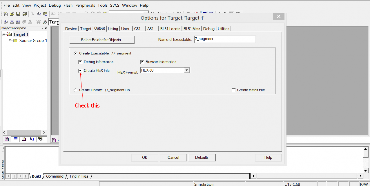
  3. Right click on Target 1, select “Options for Target Target 1”, click on Output tab and check the checkbox ‘Create HEX file’ then click OK.
 Working with Keil uvision Screenshot
  1. Click on File menu and click on ‘New’, write c program and save it with .c extension like ‘led_blinking.c’ (usually in same folder in which we create uVision project)
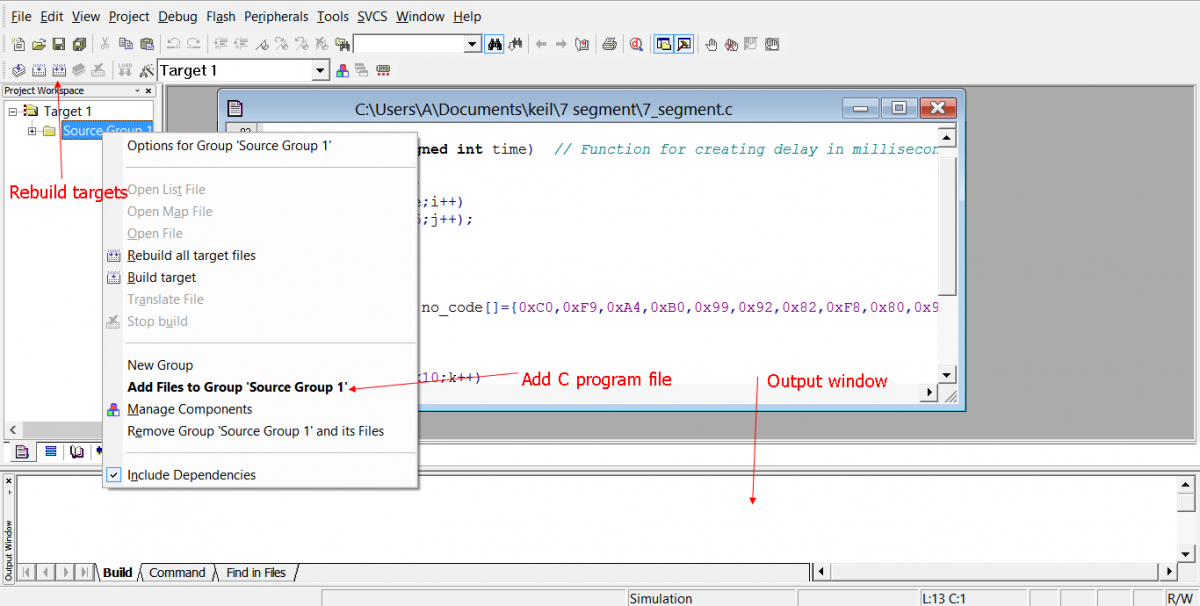
  2. Right click on ‘Source Group 1’ select ‘Add files to Group Source Group 1’ and select your c program file and click ‘Add’ then click ‘Close’.
Getting Started with 8051 -  Keil uvision4 Screenshot
  1. Now go to Project menu and click on ‘Rebuild all target Files’ or click on button as shown in above figure. In output window, you can check for any Error and Warning. It also create HEX file in same folder as c program file. We need this HEX file to program 8051 chip, explained in next section.

So at the end of this section, we have the HEX file of c program which we want to run through 8051 microcontroller.

Burning the 8051 Microcontroller

This is also called “Programming the microcontroller” or “transferring program to microcontroller”. Here we should note that microcontroller doesn’t understand the c-program or high-level language, that’s why we need a HEX file. HEX file is in machine level language, which microcontroller understands. For this purpose we have checked the “Create HEX file” in step 3 above to generate the HEX file. Now we have HEX file and 8051 chip, but how to transfer it? For that purpose we need a hardware which is called ‘Burner’ or ‘Programmer’.

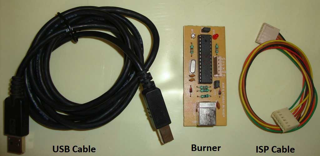
There are many types of Burner hardware available in the market, and we can also build it, you can find many tutorials on the Internet on “Building the 8051 burner”. But if you are a beginner, I recommend you to buy instead of building. They are available in the market at reasonable price ($5 to $10). ISP (In System Programming) is the simple and best way to program the microcontroller. In ISP programmer, you do not need to take out the microcontroller from breadboard each time to program it.
Getting Started with 8051 Microcontroller

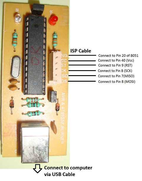
It’s very easy to connect with 8051 microcontroller, simply connect MOSI (data input) line to MOSI of 8051, MISO (data output) line to MISO and so on, like in below diagram. It can be connected through ISP cable. And connect USB cable to computer.

USB Programmer
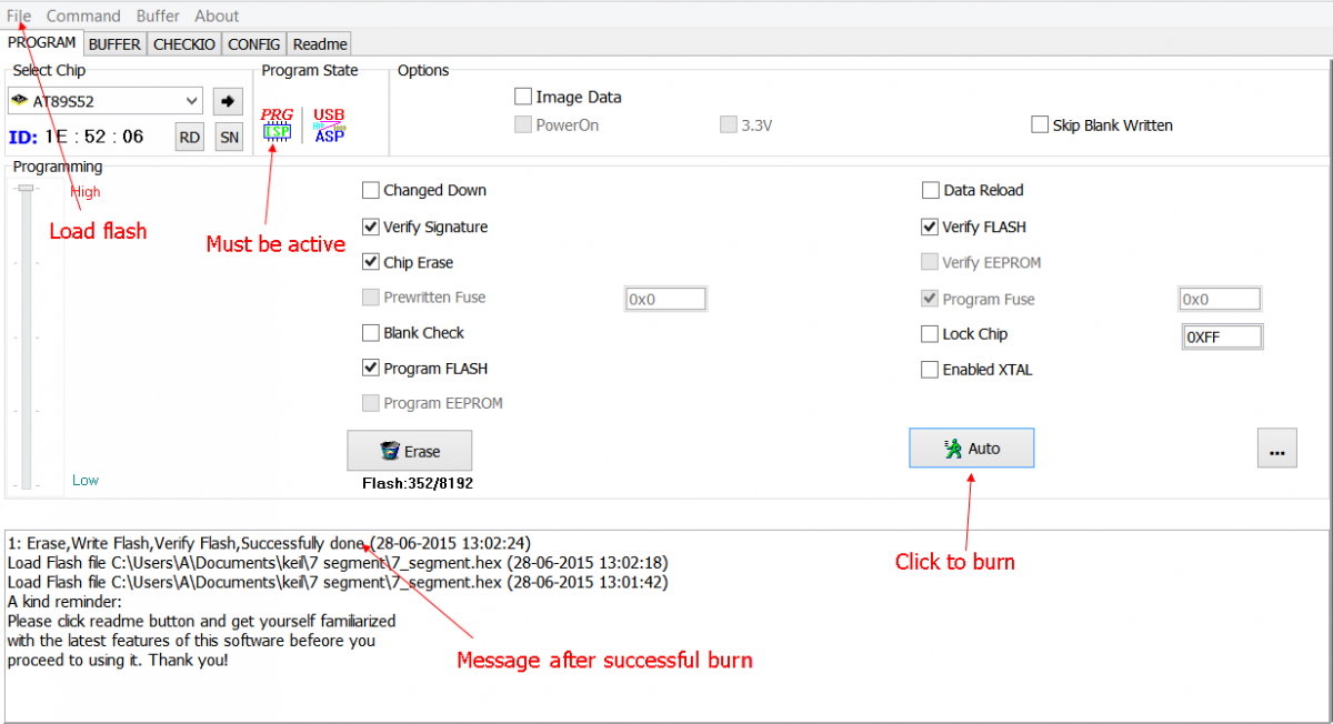
So after all the connections, how we will transfer the code to microcontroller? For that we need Burner software which will burn the Flash memory of 8051 chip. There are many softwares available like Flash magic, ProgISP etc. I recommend ProgISP, Below is the snap shot of ProgISP software. Here are Steps to burn:
  1. Download ProgISP and install drivers, run the .exe file.
  2. Check the checkboxes according to diagram.
  3. Select your chip from ‘Select Chip’ dropdown,
  4. Click on File menu, select Load Flash, select your HEX file click Open,
  5. And finally click on Auto button in ProgISP. It will burn you program into chip.
PROGISP Screenshot
Remember PROGISP icon should be active, if it is inactive or grey, means drivers haven’t been installed properly or there is some problem.
You may find some problem to install the driver in Windows 7, vista and 8, you can find solution here. Or you can use some other software to burn 8051 Microcontroller.

What's next?
Once you get started with 8051 microcontroller, start working on some 8051 microcontroller projects. Here are few experiments for beginners:

งานที่ 18 https://circuitdigest.com/microcontroller-projects/keypad-interfacing-with-8051-microcontroller

4x4 Matrix Keypad Interfacing with 8051 Microcontroller

EMBEDDED
ByJayant 9
4x4 Matrix Keypad Interfacing with 8051 Microcontroller4x4 Matrix Keypad Interfacing with 8051 Microcontroller
Keypads are widely used input devices being used in various electronics and embedded projects. They are used to take inputs in the form of numbers and albhabets, and feed the same into system for further processing. In this tutorial we are going to interface a 4x4 matrix keypad with 8051 microcontroller

4X4 Matrix Keypad

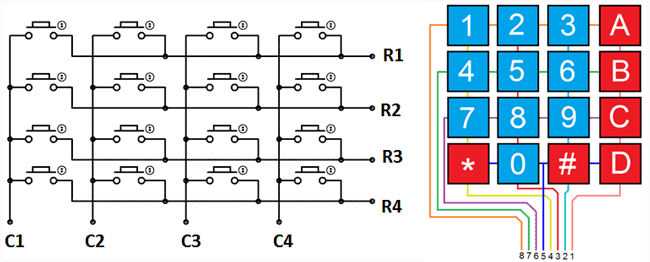
Before we interface the keypad with microcontroller, first we need to understand how it works. Matrix keypad consists of set of Push buttons, which are interconnected. Like in our case we are using 4X4 matrix keypad, in which there are 4 push buttons in each of four rows. And the terminals of the push buttons are connected according to diagram. In first row, one terminal of all the 4 push buttons are connected together and another terminal of 4 push buttons are representing each of 4 columns, same goes for each row. So we are getting 8 terminals to connect with a microcontroller.
4x4 matrix keypad

Interfacing keypad with 8051 microcontroller (AT89S52)

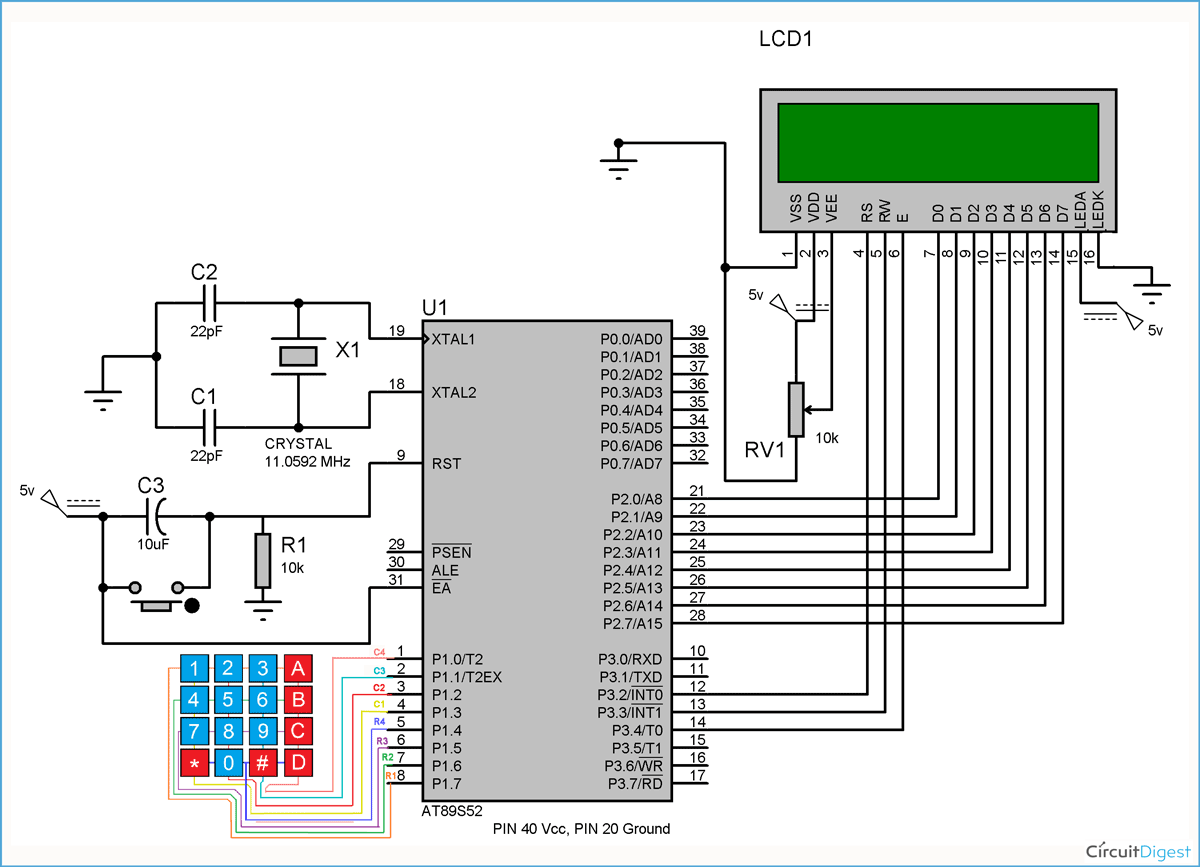
 Circuit Diagram for Keypad Interfacing with 8051 Microcontroller
First we need to interface a LCD module to display the data which will be feed through KEYPAD, so please go through “LCD Interfacing with 8051 Microcontroller” article before interfacing KEYPAD.

As shown in above circuit diagram, to interface Keypad, we need to connect 8 terminals of the keypad to any port (8 pins) of the microcontroller. Like we have connected keypad terminals to Port 1 of 8051. Whenever any button is pressed we need to get the location of the button, means the corresponding ROW an COLUMN no. Once we get the location of the button, we can print the character accordingly. 

Now the question is how to get the location of the pressed button? I am going to explain this in below steps and also want you to look at the code:
1. First we have made all the Rows to Logic level 0 and all the columns to Logic level 1.
2. Whenever we press a button, column and row corresponding to that button gets shorted and makes the corresponding column to logic level 0. Because that column becomes connected (shorted) to the row, which is at Logic level 0. So we get the column no. See main() function.
Keypad Interfacing Explanation
3. Now we need to find the Row no., so we have created four functions corresponding to each column. Like if any button of column one is pressed, we call function row_finder1(), to find the row no.
4. In row_finder1() function, we reversed the logic levels, means now all the Rows are 1 and columns are 0. Now Row of the pressed button should be 0 because it has become connected (shorted) to the column whose button is pressed, and all the columns are at 0 logic. So we have scanned all rows for 0.
Keypad Interface
5. So whenever we find the Row at logic 0, means that is the row of pressed button. So now we have column no (got in step 2) and row no., and we can print no. of that button using lcd_data function.

Same procedure follows for every button press, and we are using while(1), to continuously check, whether button is pressed or not.
Code
#include<reg51.h>
#define display_port P2      //Data pins connected to port 2 on microcontroller
sbit rs = P3^2;  //RS pin connected to pin 2 of port 3
sbit rw = P3^3;  // RW pin connected to pin 3 of port 3
sbit e =  P3^4;  //E pin connected to pin 4 of port 3
sbit C4 = P1^0;     // Connecting keypad to Port 1
sbit C3 = P1^1;
sbit C2 = P1^2;
sbit C1 = P1^3;
sbit R4 = P1^4;
sbit R3 = P1^5;
sbit R2 = P1^6;
sbit R1 = P1^7;
void msdelay(unsigned int time)  // Function for creating delay in milliseconds.
{
    unsigned i,j ;
    for(i=0;i<time;i++)    
    for(j=0;j<1275;j++);
}
void lcd_cmd(unsigned char command)  //Function to send command instruction to LCD
{
    display_port = command;
    rs= 0;
    rw=0;
    e=1;
    msdelay(1);
    e=0;
}
void lcd_data(unsigned char disp_data)  //Function to send display data to LCD
{
    display_port = disp_data;
    rs= 1;
    rw=0;
    e=1;
    msdelay(1);
    e=0;
}
 void lcd_init()    //Function to prepare the LCD  and get it ready
{
    lcd_cmd(0x38);  // for using 2 lines and 5X7 matrix of LCD
    msdelay(10);
    lcd_cmd(0x0F);  // turn display ON, cursor blinking
    msdelay(10);
    lcd_cmd(0x01);  //clear screen
    msdelay(10);
    lcd_cmd(0x81);  // bring cursor to position 1 of line 1
    msdelay(10);
}
void row_finder1() //Function for finding the row for column 1
{
R1=R2=R3=R4=1;
C1=C2=C3=C4=0;
if(R1==0)
lcd_data('1');
if(R2==0)
lcd_data('4');
if(R3==0)
lcd_data('7');
if(R4==0)
lcd_data('*');
}
void row_finder2() //Function for finding the row for column 2
{
R1=R2=R3=R4=1;
C1=C2=C3=C4=0;
if(R1==0)
lcd_data('2');
if(R2==0)
lcd_data('5');
if(R3==0)
lcd_data('8');
if(R4==0)
lcd_data('0');
}
void row_finder3() //Function for finding the row for column 3
{
R1=R2=R3=R4=1;
C1=C2=C3=C4=0;
if(R1==0)
lcd_data('3');
if(R2==0)
lcd_data('6');
if(R3==0)
lcd_data('9');
if(R4==0)
lcd_data('#');
}
void row_finder4() //Function for finding the row for column 4
{
R1=R2=R3=R4=1;
C1=C2=C3=C4=0;
if(R1==0)
lcd_data('A');
if(R2==0)
lcd_data('B');
if(R3==0)
lcd_data('C');
if(R4==0)
lcd_data('D');
}
void main()
{
    lcd_init();
    while(1)
    {    
        msdelay(30); 
        C1=C2=C3=C4=1;
          R1=R2=R3=R4=0;
          if(C1==0)
          row_finder1();
          else if(C2==0)
           row_finder2();
           else if(C3==0)
        row_finder3();
        else if(C4==0)
        row_finder4();
    }
}

งานที่ 17 https://circuitdigest.com/microcontroller-projects/servo-motor-interfacing-with-8051

Servo Motor Interfacing with 8051 Microcontroller

EMBEDDED
ByJayant 14
Servo Motor Interfacing with 8051 MicrocontrollerServo Motor Interfacing with 8051 Microcontroller
Servo motors are very useful in electronics and embedded systems. You can find the use of Servo motor everywhere around you, they are used in toys, robots, CD tray of computer, cars, aeroplane etc. The reason of this wide scope is that, servo motor is very reliable and precise. We can rotate it to any particular angle. They are available in wide range, form high torque motor to low torque motors. In this tutorial we are going to interface a servo motor to 8051 microcontroller (AT89S52).

First we need to understand the working principle of servo motors. Servo motor works on PWM (Pulse width modulation) principal, means its angle of rotation is controlled by the duration of applied pulse to its Control PIN. Basically servo motor is made up of DC motor which is controlled by a variable resistor (potentiometer) and some gears. High speed force of DC motor is converted into torque by Gears. We know that WORK= FORCE X DISTANCE, in DC motor Force is less and distance (speed) is high and in Servo, force is High and distance is less. Potentiometer is connected to the output shaft of the Servo, to calculate the angle and stop the DC motor on required angle.

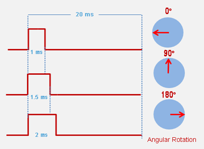
Servo motor can be rotated from 0 to 180 degree, but it can go up to 210 degree, depending on the manufacturering. This degree of rotation can be controlled by applying a LOGIC level 1 pulse for a duration between 1ms to 2ms. A 1 ms can rotate servo to 0 degree, 1.5ms can rotate to 90 degree and 2 ms pulse can rotate it to 180 degree. Duration between 1 to 2 ms can rotate Servo motor to any angle between 0 to 180 degree.
Servo Angular Rotation

Circuit Diagram and Working Explanation

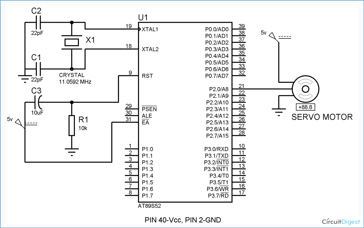
 8051 Servo Motor Interfacing Circuit Diagram
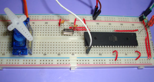
Servo motor has three wires Red for Vcc (power supply), Brown for Ground, and Orange is control wire. Control wire can be connected to 8051, we have connected it to Pin 2.1 of 8051. Now we have to keep this pin to Logic 1 for 1ms to rotate it 0 degree, 1.5ms for 90 degree, 2 ms for 180 degree. We have used on chip Timers of 8051 to create delay. We have created delay of 50us through the function “servo_delay”, and used “for” loop to create delay in multiple of 50us.

We are using Timer 0 and in Mode 1, so we have put 01H in TMOD register. Mode 1 is 16 bit timer mode and TH0 contain High byte and TL0 contain Low byte of 16 bit timer. We have put FFD2 in 16 bit timer register, FF in TH0 and D2 in TL0. Putting FFD2 will create the delay of approx. 50 us with the crystal of 11.0592MHz. TR0 and TF0 are the bits of TCON register, TR pin used to start timer when set and stop when reset(0). TF is overflow flag, set by hardware when overflow and need to reset it by software. Basically TF tells the completion of Timer, and set by hardware when 16 timer transit from FFFFH to 0000H. You can read about the “8051 Timers” to understand the calculation of value in timers registers, to create the 50 us delay.

Now when measured from CRO, 13 loops of servo_delay function will give the delay of 1ms, so we have started from 1ms (13 loops) and gone to 2 ms (26 loops) to rotate the servo from 0 to 180 degree. But we have slowly incremented the delay from 1ms, we have divided 1ms to 2 ms window into 7 parts like 1.14ms, 1.28 ms, 1.42ms and so on, so the servo will rotate in multiple of approx. 26 degrees(180/7). After 180 it will automatically return to 0 degree.
Code
// C program for interfacing servo motor with 8051 microcontroller
#include<reg51.h>
sbit output=P2^0;
void msdelay(unsigned int time)  // Function for creating delay in milliseconds.
{
    unsigned i,j ;
    for(i=0;i<time;i++)    
    for(j=0;j<1275;j++);
}
void servo_delay(int times)     // Creating Delay in multilple of 50us using 8051 Timers
{
    int m;
    for(m=0;m<times;m++)
    {
        TH0=0xFF;
        TL0=0xD2;
        TR0=1;
        while(TF0==0);
        TF0=0;
        TR0=0;
    }
}
void main()
{
    int n;
    TMOD=0x01;                // Selecting Timer 0, Mode 1
    output=0;
    while(1)
    {
        for(n=13;n<28;n=n+2)
        {
            output=1;
            servo_delay(n);     
            output=0;
            servo_delay(260);
            msdelay(200);
        }
    }
}