วันพฤหัสบดีที่ 7 กุมภาพันธ์ พ.ศ. 2562

งานที่ 16 https://circuitdigest.com/microcontroller-projects/stepper-motor-interfacing-with-8051

Stepper Motor Interfacing with 8051 Microcontroller
EMBEDDED
ByJayant 1
Stepper Motor Interfacing with 8051 MicrocontrollerStepper Motor Interfacing with 8051 Microcontroller
Stepper motor is brushless DC motor, which can be rotated in small angles, these angles are called steps. Generally stepper motor use 200 steps to complete 360 degree rotation, means its rotate 1.8 degree per step. Stepper motor used in many devices which needs precise rotational movement like robots, antennas, hard drives etc. We can rotate stepper motor to any particular angle by giving it proper instructions.

Stepper motors are basically two types: Unipolar and Bipolar. Unipolar stepper motor generally has five or six wire, in which four wires are one end of four stator coils, and other end of the all four coils is tied together which represents fifth wire, this is called common wire (common point). Generally there are two common wire, formed by connecting one end of the two-two coils as shown in below figure. Unipolar stepper motor is very common and popular because of its ease of use.
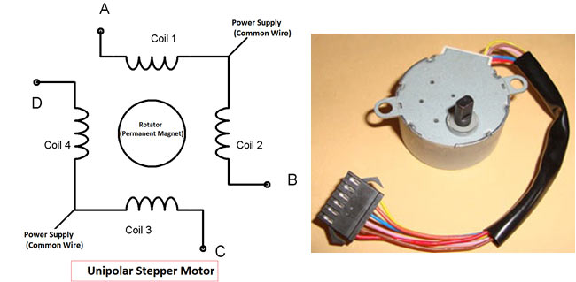
Unipolar Stepper Motor
In Bipolar stepper motor there is just four wires coming out from two sets of coils, means there are no common wire.

Stepper motor is made up of a stator and a rotator. Stator represents the four electromagnet coils which remain stationary around the rotator, and rotator represents permanent magnet which rotates. Whenever the coils energised by applying the current, the electromagnetic field is created, resulting the rotation of rotator (permanent magnet). Coils should be energised in a particular sequence to make the rotator rotate. On the basis of this “sequence” we can divide the working method of Unipolar stepper motor in three modes: Wave drive mode, full step drive mode and half step drive mode.

Wave drive mode: In this mode one coil is energised at a time, all four coil are energised one after another. It produces less torque in compare with Full step drive mode but power consumption is less. Following is the table for producing this mode using microcontroller, means we need to give Logic 1 to the coils in the sequential manner.

Steps
A
B
C
D
1
1
0
0
0
2
0
1
0
0
3
0
0
1
0
4
0
0
0
1
 

Full Drive mode: In this, two coil are energised at the same time producing high torque. Power consumption is higher. We need to give Logic 1 to two coils at the same time, then to the next two coils and so on.
Steps
A
B
C
D
1
1
1
0
0
2
0
1
1
0
3
0
0
1
1
4
1
0
0
1
 

Half Drive mode: In this mode one and two coils are energised alternatively, means firstly one coil is energised then two coils are energised then again one coil is energised then again two, and so on. This is combination of full and wave drive mode, and used to increase the angular rotation of the motor.
Steps
A
B
C
D
1
1
0
0
0
2
1
1
0
0
3
0
1
0
0
4
0
1
1
0
5
0
0
1
0
6
0
0
1
1
7
0
0
0
1
8
1
0
0
1

Interfacing Stepper Motor with 8051 Microcontroller

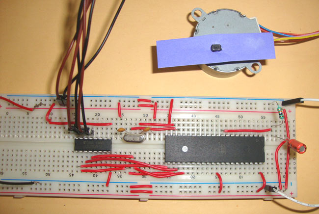
Interfacing with 8051 is very easy we just need to give the 0 and 1 to the four wires of stepper motor according to the above tables depending on which mode we want to run the stepper motor. And rest two wires should be connected to a proper 12v supply (depending on the stepper motor). Here we have used the unipolar stepper motor. We have connected four ends of the coils to the first four pins of port 2 of 8051 through the ULN2003A.
 8051 Stepper Motor Interfacing Circuit Diagram
8051 doesn’t provide enough current to drive the coils so we need to use a current driver IC that is ULN2003A. ULN2003A is the array of seven NPN Darlington transistor pairs. Darlington pair is constructed by connecting two bipolar transistors to achieve high current amplification. In ULN2003A, 7 pins are input pins and 7 pins are output pins, two pins are for Vcc (power supply) and Ground. Here we are using four input and four output pins. We can also use L293D IC in place of ULN2003A for current amplification.

You need to find out four coil wires and two common wires very carefully otherwise motor will not rotate. You can find it out by measuring resistance using multimeter, multimeter won’t show any readings between the wires of two phases. Common wire and the other two wire in the same phase should show the same resistance, and the two end points of the two coils in the same phase will show the twice resistance in compared with resistance between common point and one end point.

Troubleshooting

If your motor is not rotating OR vibrating but not rotating, then you must check the following checklist:
  1. First check the circuit connections and code.
  2. If the circuit and code is ok, then check that the stepper motor gets proper supply voltage (generally 12v), otherwise it just vibrate but not rotate.
  3. If supply is fine, then check the four coil end points which in connected to ULN2003A. First find the two common end points and connect them to 12v, then connect the remaining four wires to ULN2003A and try every possible combination until motor get started. If you wouldn’t connect them in proper order then the motor just vibrate instead of rotating.

Here is the code for Wave step mode and full wave step mode, you can easily calculate the value for PORT P2 for the half wave mode.
Code
// Wave drive Mode
#include<reg51.h>
void msdelay(unsigned int time)
    {
        unsigned i,j ;
        for(i=0;i<time;i++)    
        for(j=0;j<1275;j++);
    }
void main()
{
    while(1)
    {
        P2=0x01;            // 0001 P2_0=1,P2_1=0,P2_2=0,P2_3=0
        msdelay(1);
        P2=0x02;           //0010
        msdelay(1);
        P2=0x04;           //0100
        msdelay(1);
        P2=0x08;           //1000
        msdelay(1);
    }
}
// Full drive Mode
#include<reg51.h>
void msdelay(unsigned int time)
    {
    unsigned i,j ;
    for(i=0;i<time;i++)    
    for(j=0;j<1275;j++);
    }
void main()
{
    while(1)
    {
         P2 = 0x03;     //0011     P2_0=1,P2_1=1,P2_2=0,P2_3=0
        msdelay(1);
        P2 = 0x06;         //0110
        msdelay(1);
        P2 = 0x0C;         //1100
        msdelay(1);
        P2 = 0x09;         //1001
        msdelay(1);
    }
}

งานที่ 15 https://circuitdigest.com/microcontroller-projects/gsm-module-interfacing-with-8051-at89s52

GSM Module Interfacing with 8051 Microcontroller

EMBEDDED
ByJayant 22
GSM Module Interfacing with 8051 Microcontroller (AT89S52)GSM Module Interfacing with 8051 Microcontroller (AT89S52)
GSM module is used in many communication devices which are based on GSM (Global System for Mobile Communications) technology. It is used to interact with GSM network using a computer. GSM module only understands AT commands, and can respond accordingly. The most basic command is “AT”, if GSM respond OK then it is working good otherwise it respond with “ERROR”. There are various AT commands like ATA for answer a call, ATD to dial a call, AT+CMGR to read the message, AT+CMGS to send the sms etc. AT commands should be followed by Carriage return i.e. \r (0D in hex), like “AT+CMGS\r”. We can use GSM module using these commands.

GSM Interfacing with 8051

Instead of using PC, we can use microcontrollers to interact with GSM module and LCD to get the response from GSM module. So we are going to interface GSM with a 8051 microcontroller (AT89S52). It’s very easy to interface GSM with 8051, we just need to send AT commands from microcontroller and receive response from GSM and display it on LCD. We can use microcontroller’s serial port to communicate with GSM, means using PIN 10 (RXD) and 11 (TXD).
GSM Module SIM900A
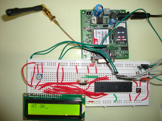
First we need to connect LCD to 8051, you can learn this from here: LCD Interfacing with 8051 Microcontroller. Then we need to connect GSM module to 8051, now here we should pay some attention. First you need to check that whether your GSM module is capable of working at TTL logic or it can only work with RS232. Basically if your module has RX and TX (with GND) Pins on board then it can work on TTL logic. And If it don’t have any RX,TX pins and only have a RS232 port (serial port with 9) then you need to use MAX232 IC to connect serial port to the microcontroller. Basically MAX232 used to convert serial data into TTL logic because Microcontroller can only work on TTL logic. But if GSM module has RX, TX pins then you don’t need to use MAX232 or any serial converter, you can directly connect RX of GSM to TX (PIN 11) of 8051 and TX of GSM to RX (PIN 10) of 8051. In our case I have used SIM900A moduleand it has RX, TX pins so I haven’t used MAX232.
 Circuit Diagram for GSM Interfacing with 8051 Microcontroller
Circuit Diagram for GSM interfacing with AT89S52 microcontroller is shown in above figure. Now after the connection, we just need to write program to send AT commands to GSM and receive its response on LCD. There are many AT commands as described above, but our scope of this article is just to interface GSM with 8051, so we are just going to send command “AT” followed by “\r” (0D in hex). This will give us a response “OK”. But you can extend this program to use all the facilities of GSM.

Code explanation

Besides all the LCD related functions, here we have used Serial port and timer mode register (TMOD). You  can learn about LCD functions and other code by going through our 8051 projects section, here I am explaining about serial communication related code functions:
GSM_init() function:
This function is use to set the Baudrate for microcontroller. Baudrate is nothing but the Bits/second transmitted or received. And we need to match the baudrate of 8051 to the Baud rate of GSM module i.e. 9600. We have used the Timer 1 in Mode 2 (8-bit auto-reload mode) by setting the TMOD register to 0X20 and Higher byte of Timer 1(TH1) to 0XFD to get the baud rate of 9600. Also SCON register is used to set the mode of serial communication, we have used Mode1 (8-bit UART) with receiving enabled.
GSM_write Function:
SBUF (serial buffer special function register) is used for serial communication, whenever we want to send any byte to serial device we put that byte in SBUF register, when the complete byte has been sent then TI bit is set by hardware. We need to reset it for sending next byte. It’s a flag that indicates that byte has been sent successfully. TI is the second bit of SCON register. We have sent “AT” using this function.
GSM_read function:
Same as sending, whenever we receive any byte from external device that byte is put in SBUF register, we just need to read it. And whenever the complete byte has been received RI bit is set by hardware. We need to reset it for receiving next byte. RI is the first bit of SCON register. We have read response “OK” using this function.
Code
#include<reg52.h>
#define display_port P2      //Data pins connected to port 2 on microcontroller
sbit rs = P3^2;  //RS pin connected to pin 2 of port 3
sbit rw = P3^3;  // RW pin connected to pin 3 of port 3
sbit e =  P3^4;  //E pin connected to pin 4 of port 3
int k;
unsigned char str[26];
void GSM_init()            // serial port initialization 
{
    TMOD=0x20;            // Timer 1 selected, Mode 2(8-bit auto-reload mode)
    TH1=0xfd;            // 9600 baudrate
    SCON=0x50;            // Mode 1(8-bit UART), receiving enabled
    TR1=1;                // Start timer
}
void msdelay(unsigned int time)  // Function for creating delay in milliseconds.
{
    unsigned m,n ;
    for(m=0;m<time;m++)    
    for(n=0;n<1275;n++);
}
void lcd_cmd(unsigned char command)  //Function to send command instruction to LCD
{
    display_port = command;
    rs= 0;
    rw=0;
    e=1;
    msdelay(1);
    e=0;
}
void lcd_data(unsigned char disp_data)  //Function to send display data to LCD
{
    display_port = disp_data;
    rs= 1;
    rw=0;
    e=1;
    msdelay(1);
    e=0;
}
 void lcd_init()    //Function to prepare the LCD  and get it ready
{
    lcd_cmd(0x38);  // for using 2 lines and 5X7 matrix of LCD
    msdelay(10);
    lcd_cmd(0x0F);  // turn display ON, cursor blinking
    msdelay(10);
    lcd_cmd(0x01);  //clear screen
    msdelay(10);
    lcd_cmd(0x80);  // bring cursor to beginning of first line
    msdelay(10);
}         
void lcd_string(unsigned char *str)    // Function to display string on LCD
{
    int i=0;
    while(str[i]!='\0')
    {
       lcd_data(str[i]);                  
       i++;
       msdelay(10);
      if(i==15) lcd_cmd(0xc2);                                          
       }
    return; 
}
void GSM_write(unsigned char ch)    // Function to send commands to GSM
{
    SBUF=ch;        // Put byte in SBUF to send to GSM
    while(TI==0);        //wait until the byte trasmission
    TI=0;            //clear TI to send next byte.      
}
 void GSM_read()     // Function to read the response from GSM
 {     
    while(RI==0);   // Wait until the byte received  
    str[k]=SBUF;    //storing byte in str array
    RI=0;           //clear RI to receive next byte
 }
void main()
{        
    k=0;
    lcd_init();                            
    GSM_init();                
    msdelay(200);
    lcd_string("Interfacing GSM with 8051");
    msdelay(200);
    lcd_cmd(0x01);            //    Clear LCD screen
    msdelay(10);                                     
    GSM_write('A');              // Sending 'A' to GSM module
    lcd_data('A');                 
    msdelay(1);
    GSM_write('T');            // Sending 'T' to GSM module
    lcd_data('T');                 
    msdelay(1);
    GSM_write(0x0d);          // Sending carriage return to GSM module            
    msdelay(50);
    while(1)
    {          
        GSM_read();
        if(str[k-1]=='O' && str[k]=='K'){
            lcd_data(0x20);                      // Write 'Space'
            lcd_data(str[k-1]);
            lcd_data(str[k]);
            break; 
        }
        k=k+1;                                            
    }
}
 

งานที่ 14 https://circuitdigest.com/microcontroller-projects/line-follower-robot-using-8051-microcontroller


Line Follower Robot using 8051 Microcontroller

EMBEDDED
BySaddam 21
Line Follower Robot using 8051 MicrocontrollerLine Follower Robot using 8051 Microcontroller
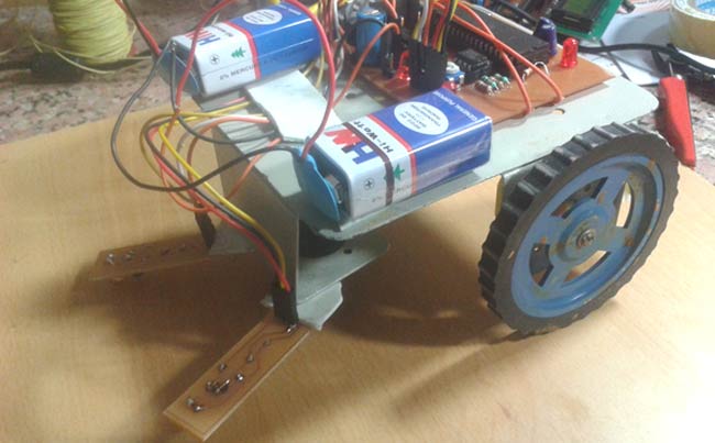
Line follower Robot is a machine which follows a line, it may be a black line or a white line. Basically two types of line follower robots are: one is black line follower which follows black line and second one is white line follower which follows white line. Line follower actually senses the line and run over it. In our previous projects, we have made a black line follower robot using arduino but this time we are going to make white line follower using 8051 microcontroller. In this tutorial, we will also cover how to make a printed circuit board for line follower robot at home in low price. 

Concept of Line Follower Robot

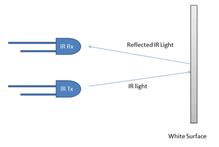
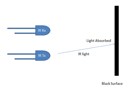
Concept of line follower is related to light. We have used the behaviour of light at black and white surface. When light fall on a white surface it will almost full reflects and in case of black surface light is absorbed by black surface. This explained behaviour of light is used in this line follower robot.
Concept of White Line Follower Robot
Concept of Black Line Follower Robot
In this line follower robot project we have used IR Transmitters and IR receivers also called photo diodes for sending and receiving light. IR transmits infrared lights. When infrared rays falls on white surface, it is reflected back and catched by photodiode and generates some voltage changes. When IR light falls on black surface light is absorbed by the black surface and not rays reflect back, so photo diode did not received any light or rays. Here in this line follower robot when sensor senses white surface then microcontroller gets 0 as input and when senses black line microcontroller gets 1 as input.

Circuit Explanation

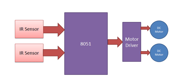
We can divide the whole line follower robot into various sections like sensor section, control section and driver section.
8051 Based Line Follower Robot Block Diagram
Sensor section: This section contains IR diodes, potentiometer, Comparator (Op-Amp) and LED’s. Potentiometer is used for setting reference voltage at comparator’s one terminal and IR sensors sense the line and provide a change in voltage at comparator’s second terminal. Then comparator compares both voltages and generates a digital signal at output. Here in this circuit we used two comparator for two sensors. LM358 is used as comparator. LM358 has inbuilt two low noise Op-amp.

Control Section: 8051 microcontroller is used for controlling whole the process of line follower robot. The outputs of comparators are connected to pin number P0.0 and P0.1 of 8051. 8051 reads these signals and send commands to driver circuit to drive line follower.

Driver section: Driver section consists motor driver and two DC motors. Motor driver is used for driving motors because microcontroller does not supply enough voltage and current to motor. So we added a motor driver circuit to get enough voltage and current for motor. Microcontroller sends commands to this motor driver and then it drive motors.

Working of Line Follower Robot using 8051

Line follower robot senses white line by using sensor and then sends signals to microcontroller. Then microcontroller drives the motor according to sensors' output.

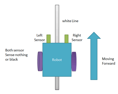
Here in this project we are using two IR sensors pair. Suppose we are calling left sensor and right sensor of IR sensor Pair, then both left and right sensors sense nothing or black line then robot move forward.
Line Follower Forward Move
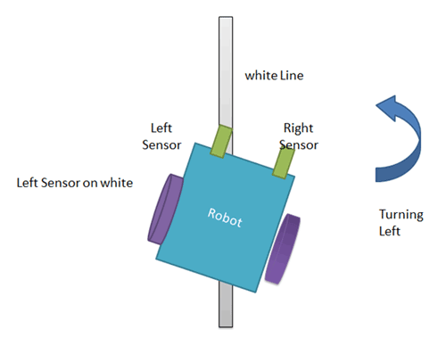
And when left sensor senses white line then robot turn left side.
Line Follower Left Turn
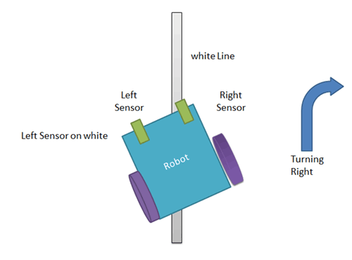
and when left sensor sense white line then robot turns to right side until both sensor comes at black line or senses nothing surface.
Line Follower Right Turn
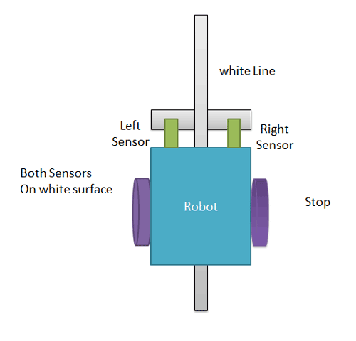
And when both sensors comes on white line, robot stop.
Line Follower Robot Stop

8051 Based Line Follower Robot Circuit

Circuit is very simple for this line follower robot. Output of comparators is directly connected to pin number P0.0 and P0.1 of microcontroller. And motor driver’s input pin 2, 7, 10 and 15 is connected at pin number P2.3, P2.2, P2.1 and P2.4 respectively. And one motor is connected at output pin of motor driver 3 and 6 and another motor is connected at 11 and 14. 
 Line Follower Robot Circuit Diagram using 8051 Microcontroller

Programming Explanation

In program first of all we defines input and output pin. And then in main function we checks inputs and sends output according to inputs to output pin for driving motor. For checking input pin we used “if” statements.

There are four conditions in this line follower. We have used two sensor namely left sensor and right sensor.
Input
Output
Movement of Robot
Left Sensor
Right Sensor
Left Motor
Right Motor
LS
RS
LM1
LM2
RM1
RM2

0
0
1
0
1
0
Forward
0
1
1
0
0
0
Turn Right
1
0
0
0
1
0
Turn Left
1
1
0
0
0
0
Stop
We have writen the program according to above table conditions. See the complete code of this 8051 based line follower robot at the bottom of this page to understand the concept.

PCB Layout

Here is the PCB layout for line follower robot designed in Dip Trace Software.
8051 Line Follower PCB Layout
In this PCB layout we have designed a circuit board for line follower and 2 sticks for placing IR sensors. Check here the step by step tutorial to make the line follower robot on PCB: How to make a PCB at home
Code
// C Program for line follower robot using 8051 microcontroller
#include<reg51.h>
sbit ls=P0^0;
sbit rs=P0^1;
#define motor P2
#define forward 0x06
#define turn_left 0x82
#define turn_right 0x14
#define stop 0x00
void main()
{
    motor=stop;
    while(1)
    {
     if(ls && rs)
         motor=forward;
     else if(!ls && rs)
         motor=turn_left;
     else if(ls && !rs)
       motor=turn_right;
     else 
         motor=stop;
  }
}